MAKE Magazine Bare Bones Amplifier
Last winter, after returning to school from vacation, I turned on my computer and the boom box I had connected to it to watch some television with my computer’s TV tuner. Whilst in the middle of a particularly exciting episode of “Law & Order”, my stereo soon started to make some rather horrible noises. In a matter of moments, the RCA brand stereo that I had been using for almost 3 years to crank the tunes out of my iMac finally cut out completely, leaving me in a silent dorm room filling with the smell of burning electronics.
After taking apart the stereo, I quickly realized that I was in over my head. Like so many other things in this day and age, my stereo was not designed to be repaired, but rather to be thrown away and replaced. At the end of the semester, I put the stereo’s gutted carcass in the recycling bin on my dorm room floor, but hung onto the speakers, figuring I could buy a new amplifier instead. Unfortunately, according to my dad, a major audiophile himself, buying a new amplifier alone would set me back a pretty penny. The only other alternative would be to buy another boom box that would probably explode itself in another 3 years.
Fortunately, by a stroke of luck, this summer’s issue of MAKE Magazine (issue #23), contains a project called “Squelette, the Bare-Bones Amplifier”: a two-channel amplifier built from a pair of National Semiconductor LM1875 audio amplifier ICs and a number of discrete parts available from most RadioShacks with a well-stocked electronic parts aisle. It was exactly what I was looking for.
Perhaps the only quibble I had with the BBA, however, was its use of perf board for a base. Perf board is that printed circuit board material with all those grid holes in it and those solder pads that just don’t take solder all that well (at least for me they don’t). Not only do I not like working with perf board, but I have become somewhat addicted to using EAGLE to make my own boards and have them fabricated by companies like BatchPCB or Gold Phoenix (an unfortunate side effect of my last project).
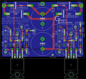
Today, I am pleased to present my schematic and board layout for my version of the MAKE Magazine Bare-Bones Amplifier, which I will soon be submitting to BatchPCB for fabrication. You can find the files, along with a bill of materials and other important documents, here. Please note, however, that there are no instructions provided. You can find instructions for building the amplifier in MAKE Magazine Issue #23.
My plan for my amplifier is to mount it inside a wooden box with a brass or aluminum bottom and back to help cool both the ICs and the transformer. A light coat of stain and some varnish, perhaps a Plexiglas lid, and I will have a stereo again. More importantly, I’ll have a stereo that I can fix myself and is supposed to sound exceptionally good.
EDIT: I decided to post my progress on the discussion board for the amplifier article. The author of the article, Ross Hershberger, saw my board layout and had this to say:
Thanks for your interest in this article and for the work that you put into adapting it to your needs. I don’t have the reader to look at your PCB layouts. I want to warn about one thing. NatSemi is very specific about the handling of the grounds in the circuit. They specify star grounding to a central point for the power supply and audio circuit grounds. The input ground reference, power supply bypass caps, feedback, etc. should all have their currents carried to the 0V star ground on separate leads. The manufacturer warns that mixing currents could lead to noise, distortion and instability. Typical PCB ground plane practice allows currents to interact in unpredictable ways. The chip has an open loop gain of 90dbs and any spurious signals on the input or feedback circuits could be amplified.
Good thing I didn’t send the files off for fabrication yet. I have to remove the ground plane and replace it with individual, dedicated lines between each grounded device and the two pins between the two 4700μF capacitors, or I’ll end up amplifying electrical noise as well. This would be so much easier if they only taught printed circuit board design at Southern Illinois University at Carbondale.
29
